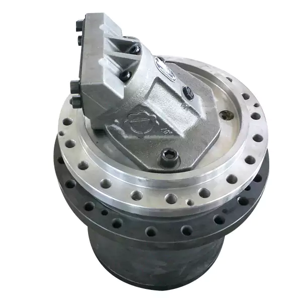
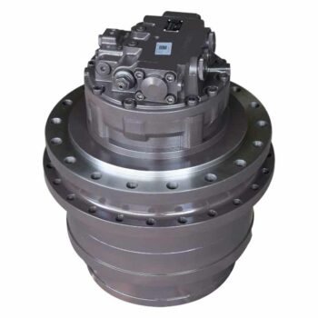
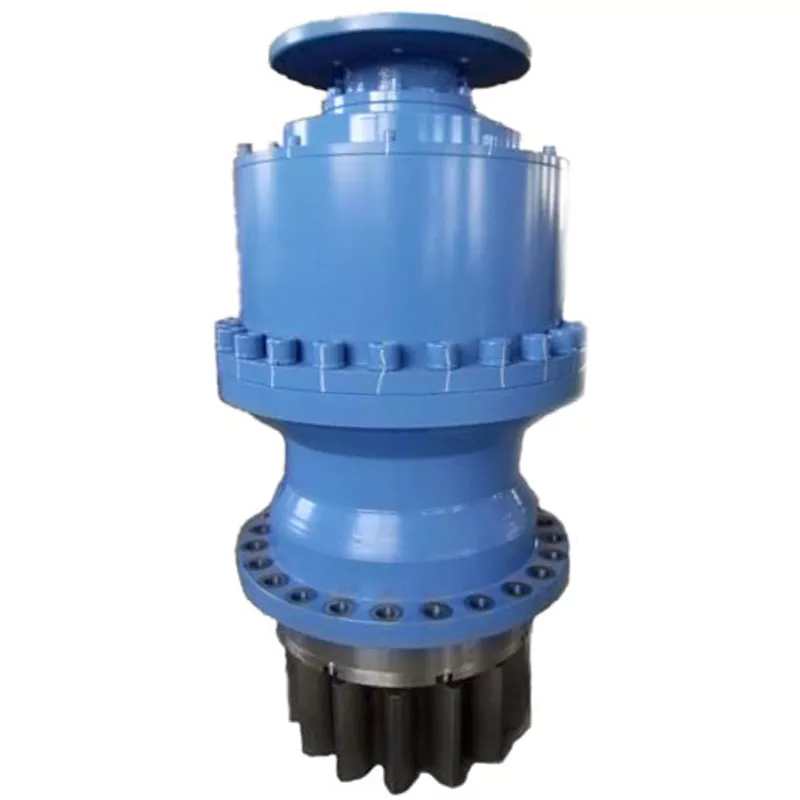
Product Description
Company Profile
We CZPT is a OEM factory, accpet customerized. Most of our products are customerzation.The product include gear housing/boxes/reducers, Iron casting products, Aluminum products. Such as auto parts, agriculture parts, and other industrial parts.
We have the most advanced testing facilities, such as spectral analyzer for rubber material chemical composition test, tensile strength testing machine, impact value tester and hardness meter, magnetic particle testing machine, sandblasting machine and heat treatment equipment. Besides, there are numerous advanced equipment in the precision machining workshop: have 23 sets CNC lathes, 10sets vertical CNC boring and milling center and 1 horizontal boring and milling center imported from Korea, 2 general milling machine, and 2 general lathes, 1 grinder, 10sets drilling and tap machines, 2 half automatic saw, and 1 Coordinate Measuring Machine (CMM), 1 Projector and 1 machining surface quality testing machine and 1 Mahr altitude instrument. Our product’s tolerance can be controlled under 0.01mm. The testing machine’s accuracy is within 0.005mm. ISO9000 has been executed.
Product Parameters
| Maximum torque: | 20,000NM |
| Maximum output speed: | <1200rpm |
| Maximum input speed: | <2500rpm |
| Ratio: | 3:1 up to 4:1 |
| Output type: | square shaft hex shaft flange |
Our Advantages
1. 20 years of experience in manufacturing and exporting
2. OEM and custom-made service
3. All kinds of castings can be manufactured according to the drawings, samples or specific industry standard
4. Strong engineering team makes high quatliy
5. The coordinated service(casting, machining and surface treatment) make lower price if possible
6. Advanced-level equipments
7. Full material testing process and quatliy control system
8. Quality assurance and delivery on time
About CZPT Industrial
| Application: | Motor, Electric Cars, Machinery, Marine, Agricultural Machinery |
|---|---|
| Function: | Change Drive Torque, Change Drive Direction, Speed Changing, Speed Reduction, Speed Increase |
| Layout: | Cycloidal |
| Samples: |
US$ 500/Piece
1 Piece(Min.Order) | Order Sample |
|---|
| Customization: |
Available
| Customized Request |
|---|
.shipping-cost-tm .tm-status-off{background: none;padding:0;color: #1470cc}
|
Shipping Cost:
Estimated freight per unit. |
about shipping cost and estimated delivery time. |
|---|
| Payment Method: |
|
|---|---|
|
Initial Payment Full Payment |
| Currency: | US$ |
|---|
| Return&refunds: | You can apply for a refund up to 30 days after receipt of the products. |
|---|

Concept of Coaxial and Parallel Shaft Arrangements in Planetary Gearboxes
Coaxial and parallel shaft arrangements refer to the orientation of the input and output shafts in a planetary gearbox:
- Coaxial Shaft Arrangement: In this arrangement, the input and output shafts are aligned along the same axis, with one shaft passing through the center of the other. This design results in a compact and space-efficient gearbox, making it suitable for applications with limited space. Coaxial planetary gearboxes are commonly used in scenarios where the gearbox needs to be integrated into a compact housing or enclosure.
- Parallel Shaft Arrangement: In a parallel shaft arrangement, the input and output shafts are positioned parallel to each other but not on the same axis. Instead, they are offset from each other. This configuration allows for greater flexibility in designing the layout of the gearbox and the surrounding machinery. Parallel shaft planetary gearboxes are often used in applications where the spatial arrangement requires the input and output shafts to be positioned in different locations.
The choice between a coaxial and parallel shaft arrangement depends on factors such as available space, mechanical requirements, and the desired layout of the overall system. Coaxial arrangements are advantageous when space is limited, while parallel arrangements offer more design flexibility for accommodating various spatial constraints.

Differences Between Inline and Right-Angle Planetary Gearbox Configurations
Inline and right-angle planetary gearbox configurations are two common designs with distinct characteristics suited for various applications. Here’s a comparison of these configurations:
Inline Planetary Gearbox:
- Configuration: In an inline configuration, the input and output shafts are aligned along the same axis. The sun gear, planetary gears, and ring gear are typically arranged in a straight line.
- Compactness: Inline gearboxes are more compact and have a smaller footprint, making them suitable for applications with limited space.
- Efficiency: Inline configurations tend to have slightly higher efficiency due to the direct alignment of components.
- Output Speed and Torque: Inline gearboxes are better suited for applications that require higher output speeds and lower torque.
- Applications: They are commonly used in robotics, conveyors, printing machines, and other applications where space is a consideration.
Right-Angle Planetary Gearbox:
- Configuration: In a right-angle configuration, the input and output shafts are oriented at a 90-degree angle to each other. This allows for a change in direction of power transmission.
- Space Flexibility: Right-angle gearboxes offer flexibility in arranging components, making them suitable for applications that require changes in direction or where space constraints prevent a straight-line configuration.
- Torque Capacity: Right-angle configurations can handle higher torque loads due to the increased surface area of gear engagement.
- Applications: They are often used in cranes, elevators, conveyor systems, and applications requiring a change in direction.
- Efficiency: Right-angle configurations may have slightly lower efficiency due to increased gear meshing complexity and potential for additional losses.
Choosing between inline and right-angle configurations depends on factors such as available space, required torque and speed, and the need for changes in power transmission direction. Each configuration offers distinct advantages based on the specific needs of the application.

Challenges and Solutions for Managing Power Transmission Efficiency in Planetary Gearboxes
Managing power transmission efficiency in planetary gearboxes is crucial to ensure optimal performance and minimize energy losses. Several challenges and solutions are involved in maintaining high efficiency:
1. Gear Meshing Efficiency: The interaction between gears can lead to energy losses due to friction and meshing misalignment. To address this, manufacturers use precision manufacturing techniques to ensure accurate gear meshing and reduce friction. High-quality materials and surface treatments are also employed to minimize wear and friction.
2. Lubrication: Proper lubrication is essential to reduce friction and wear between gear surfaces. Using high-quality lubricants with the appropriate viscosity and additives can enhance power transmission efficiency. Regular maintenance and monitoring of lubrication levels are vital to prevent efficiency losses.
3. Bearing Efficiency: Bearings support the rotating elements of the gearbox and can contribute to energy losses if not properly designed or maintained. Choosing high-quality bearings and ensuring proper alignment and lubrication can mitigate efficiency losses in this area.
4. Bearing Preload: Incorrect bearing preload can lead to increased friction and efficiency losses. Precision assembly and proper adjustment of bearing preload are necessary to optimize power transmission efficiency.
5. Mechanical Losses: Various mechanical losses, such as windage and churning losses, can occur in planetary gearboxes. Designing gearboxes with streamlined shapes and efficient ventilation systems can reduce these losses and enhance overall efficiency.
6. Material Selection: Choosing appropriate materials with high strength and minimal wear characteristics is essential for reducing power losses due to material deformation and wear. Advanced materials and surface coatings can be employed to enhance efficiency.
7. Noise and Vibration: Excessive noise and vibration can indicate energy losses in the form of mechanical inefficiencies. Proper design and precise manufacturing techniques can help minimize noise and vibration, indicating better power transmission efficiency.
8. Efficiency Monitoring: Regular efficiency monitoring through testing and analysis allows engineers to identify potential issues and optimize gearbox performance. This proactive approach ensures that any efficiency losses are promptly addressed.
By addressing these challenges through careful design, material selection, manufacturing techniques, lubrication, and maintenance, engineers can manage power transmission efficiency in planetary gearboxes and achieve high-performance power transmission systems.


editor by CX 2023-11-15